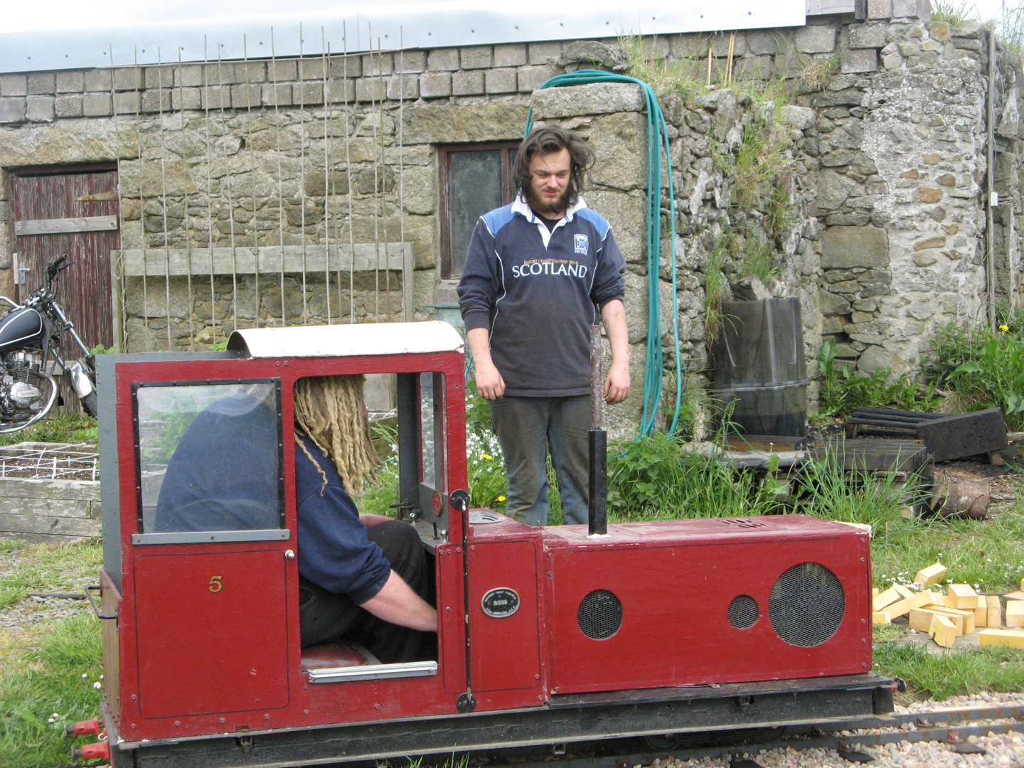
Diesel Engine No.5 'Helen'
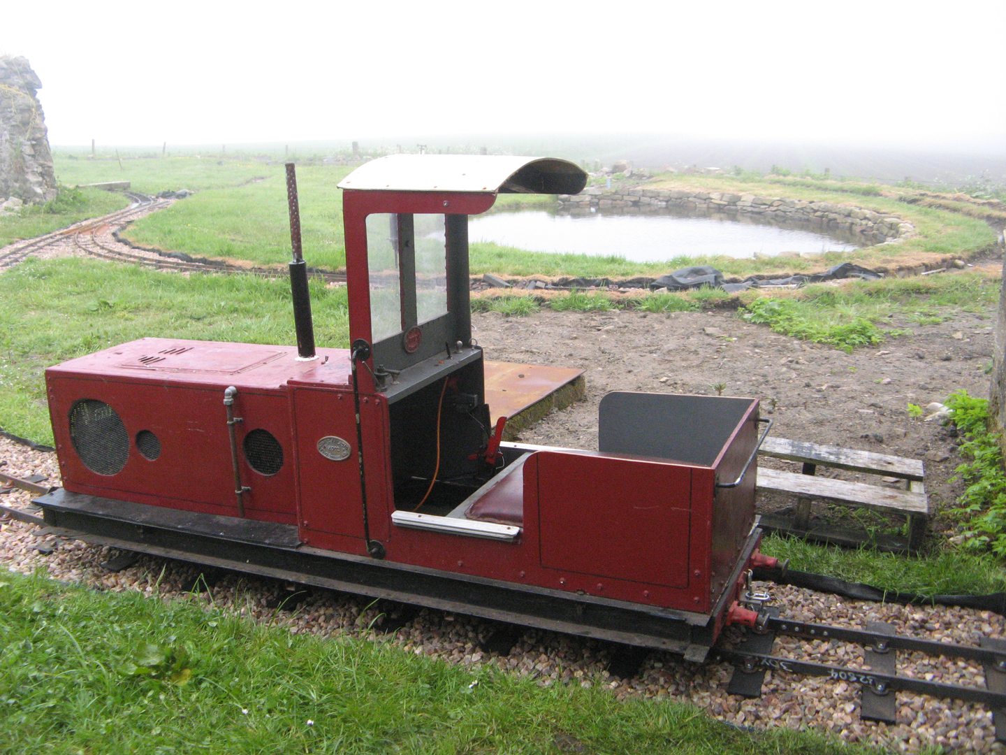
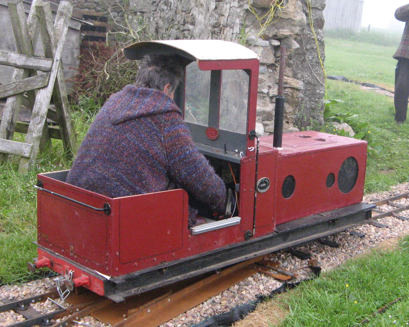
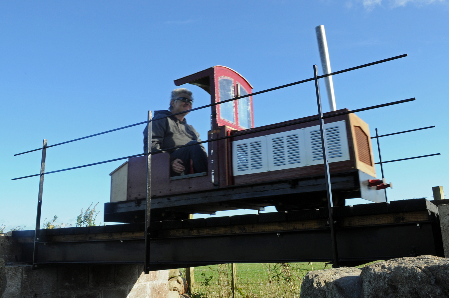 Actually petrol powered, this large 'diesel' shunter is another freelance sit-in engine. Although just about seven feet long, a bogie chassis allows it to negotiate tight curves.
When buying this engine she was referred to as 'the horrible shunter' or 'HS' for short. Following a discussion about beauty being in the eye of the beholder, Karen matched the initials HS to Helen Shapiro, so now she is more politely known as 'Helen'.
Karen redesigned the bodywork to make the cab more accessible and has added other features. There is still much hole filling to be done and a repaint is needed, but we hope you will agree 'Helen' is now a much better looking locomotive than when we bought her.
In her previous incarnation this engine was apparently used for junior driver training duties on the now sadly defunct Sanday Light Railway in Orkney. Since conversion to petrol-electric drive, she is often called upon to perform similar duties on Karen's Little Railway because she is simple to drive.
Cosmetic Changes

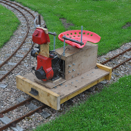
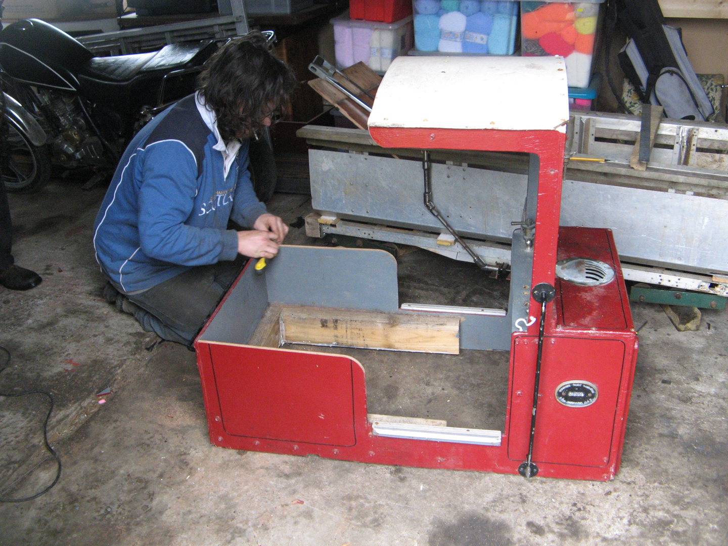
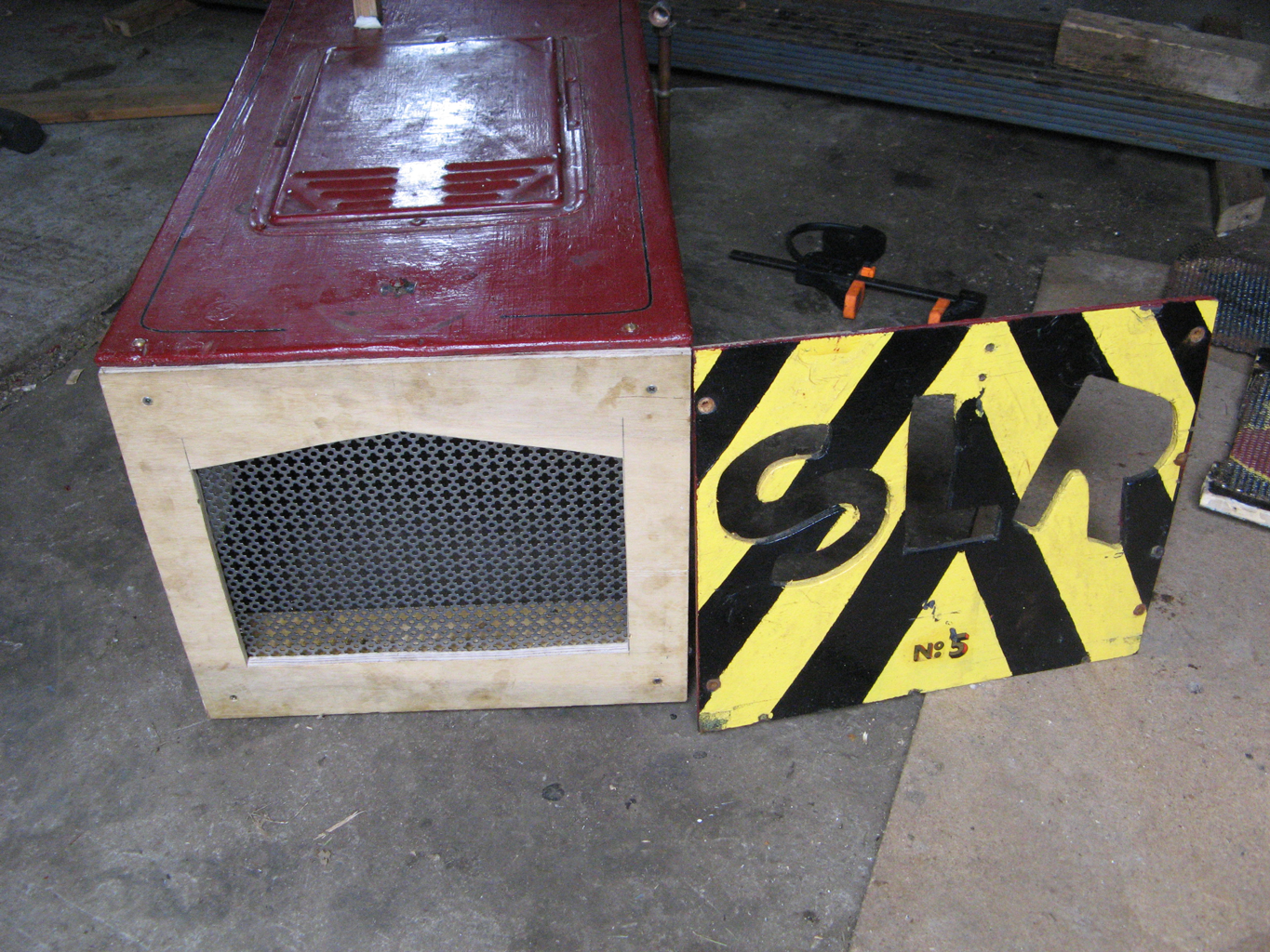
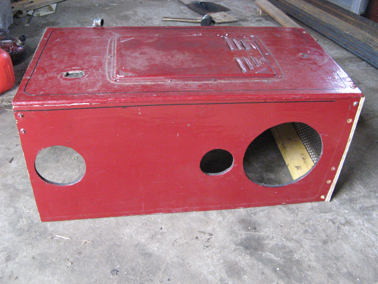
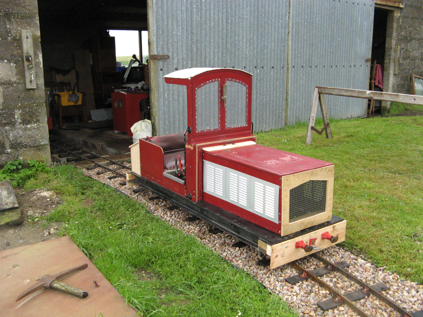
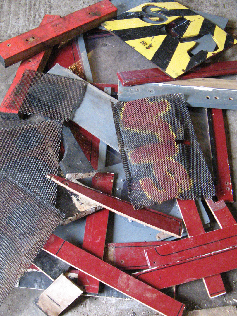
Before: Horrible Shunter

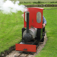
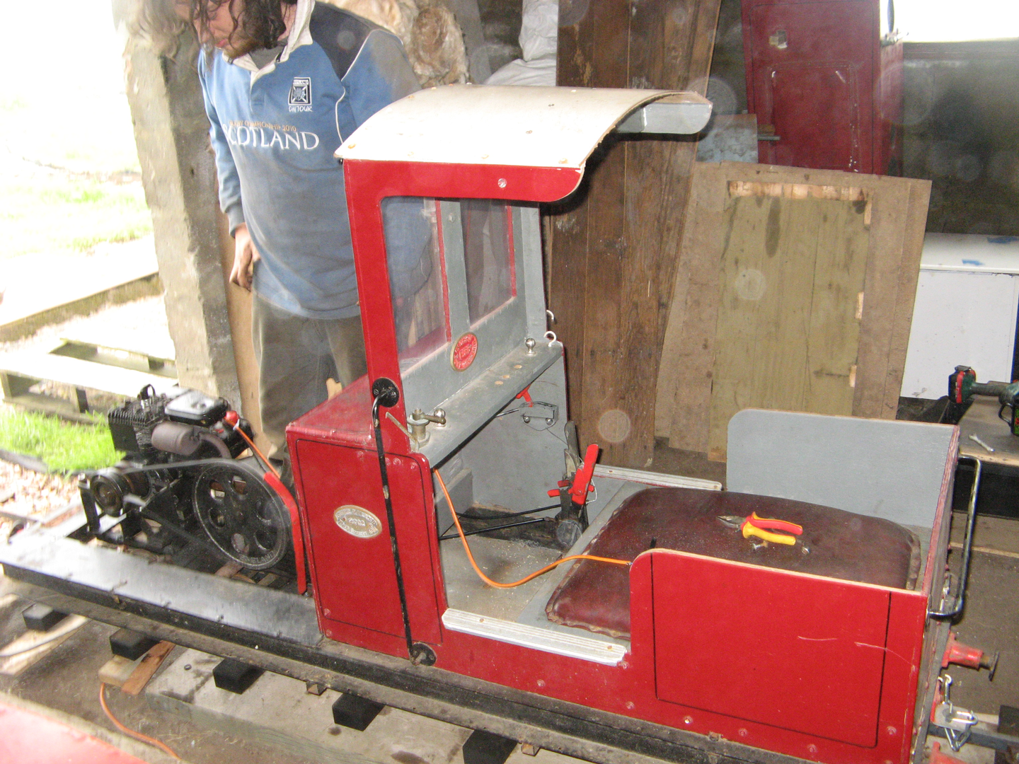
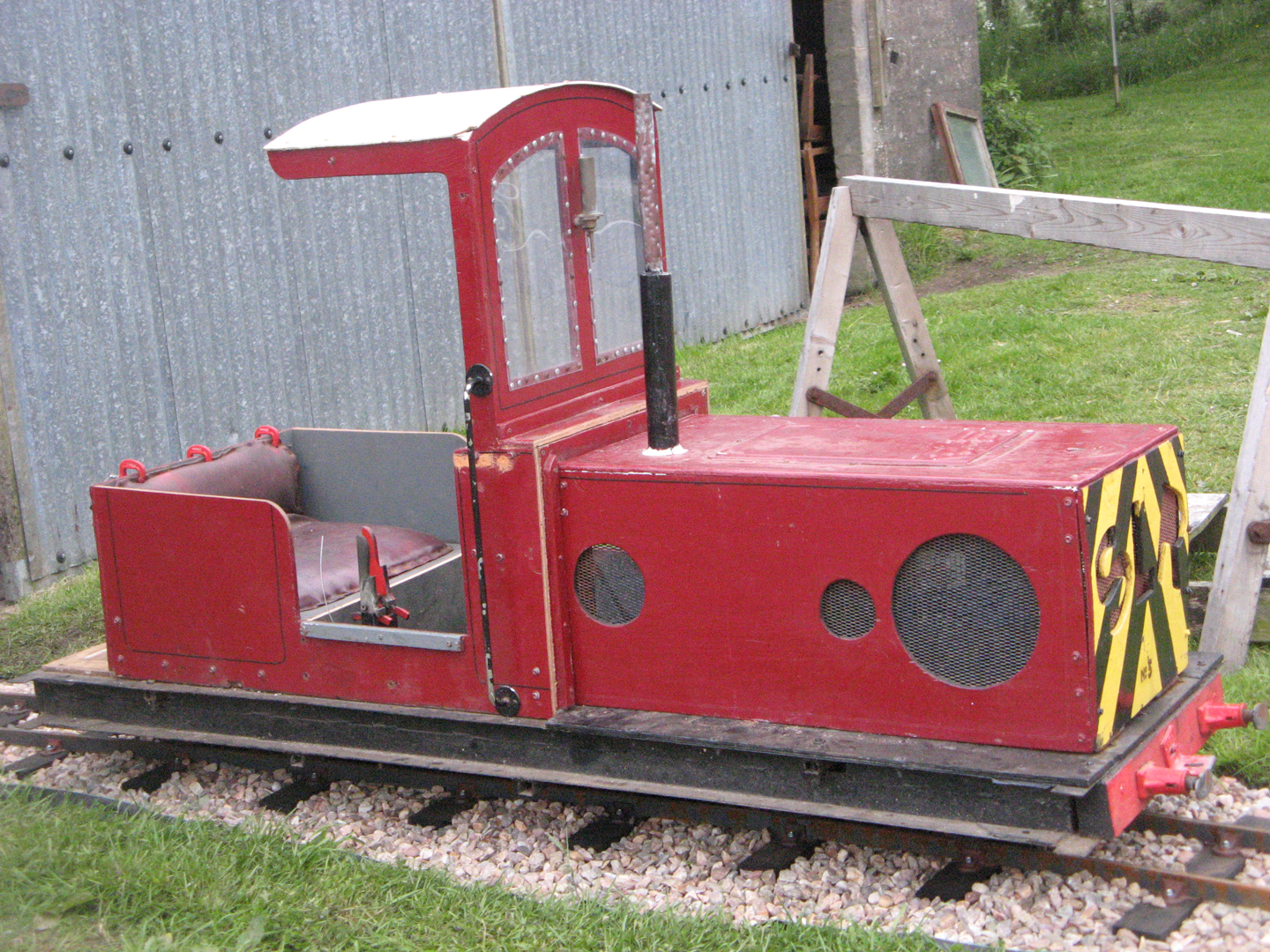
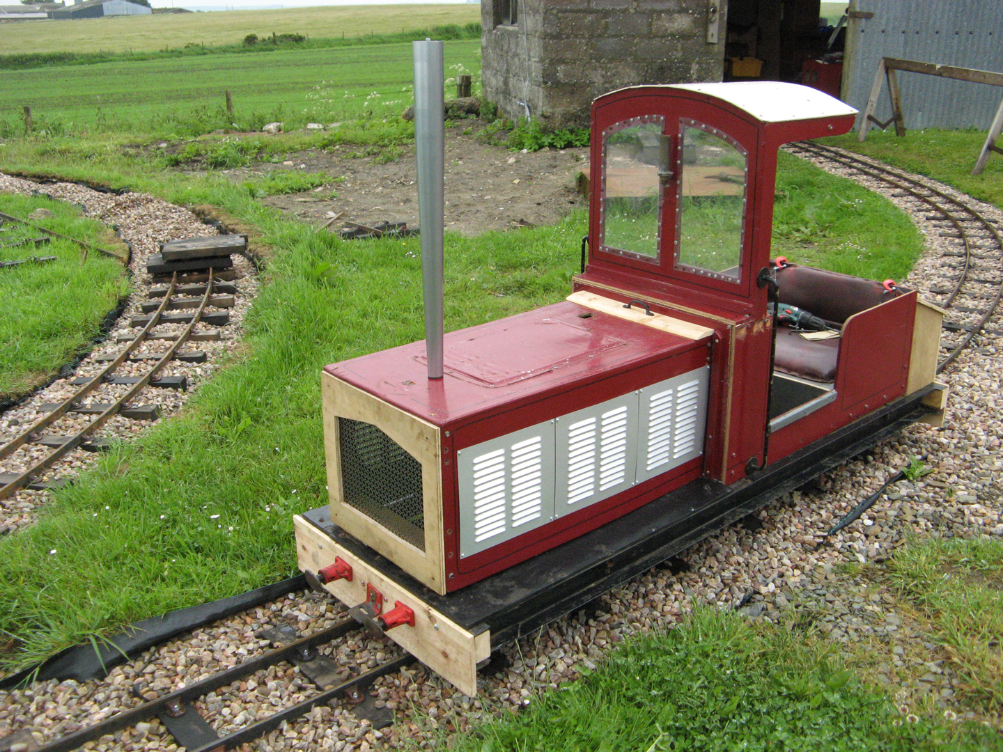
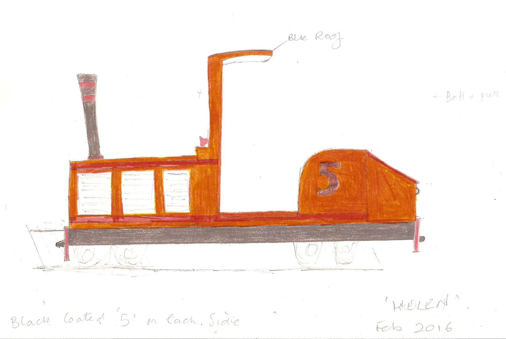
After: Helen
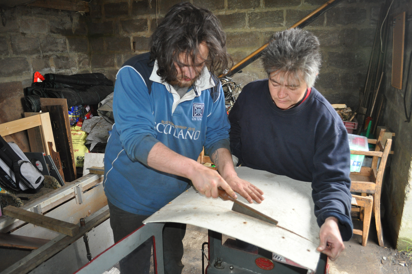
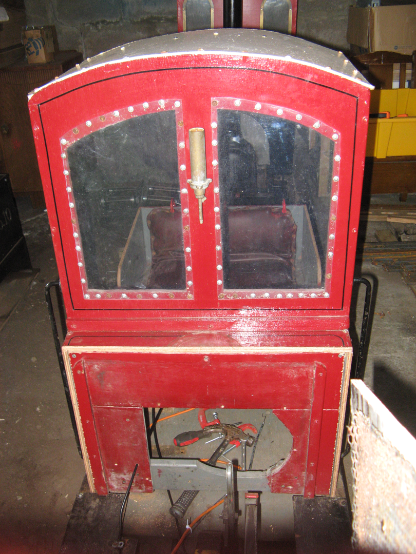
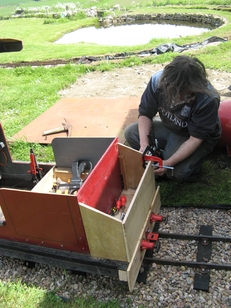
Karen wanted a railway project as she was unable to help with the basic navvying tasks. She took charge of re-designing and (with Ruarí's help) rebuilding Helen's bodywork. The plywood of the original bodywork seemed to be of decent quality so it was worth keeping, but nothing was square so modifications were generally done by eye rather than measuring.
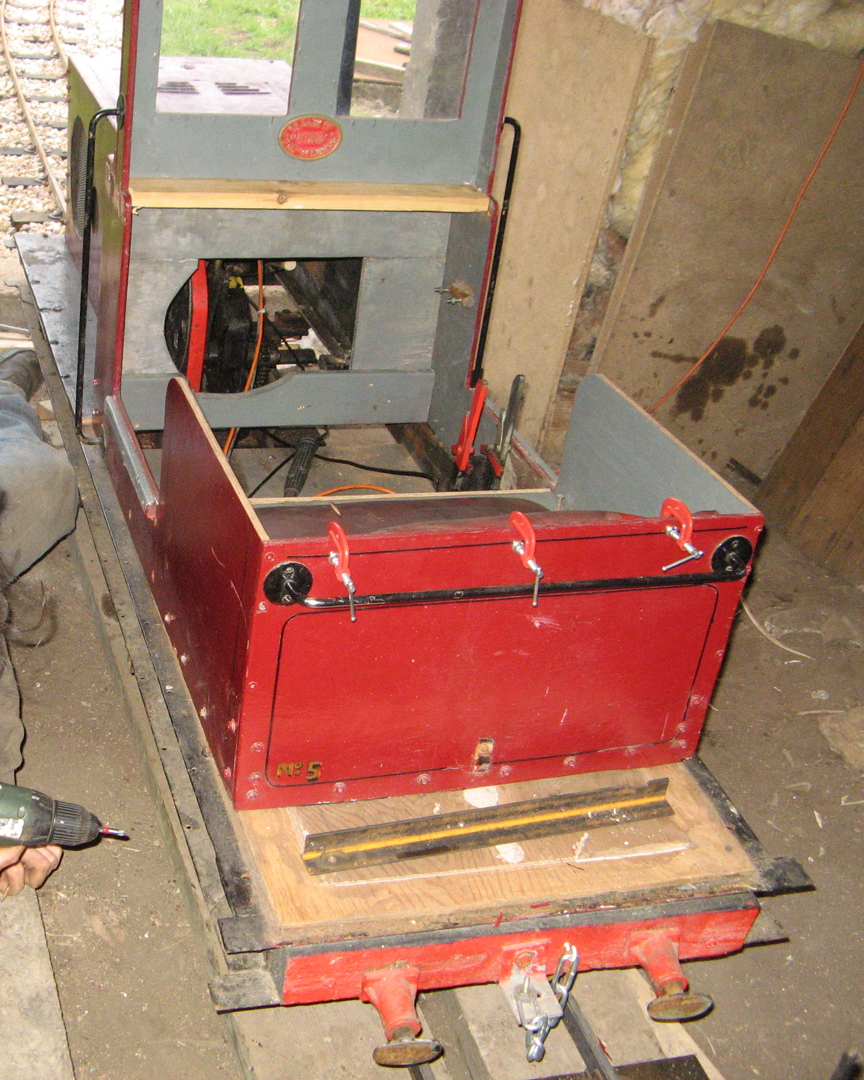
The initial idea was to modify the cab to make it more accessible so that Karen could drive this engine. Having done that, she decided to move the cab forward so that it was easier to reach the forward/reverse lever and add a boot/tool box in the space now left behind the cab. Karen said "every girl needs a handbag", and she was right......... this boot space has proved very useful for carrying tools around the railway.
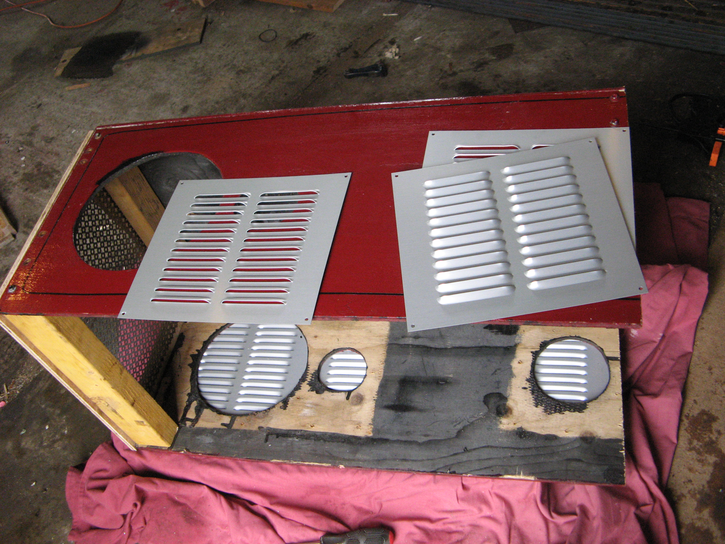
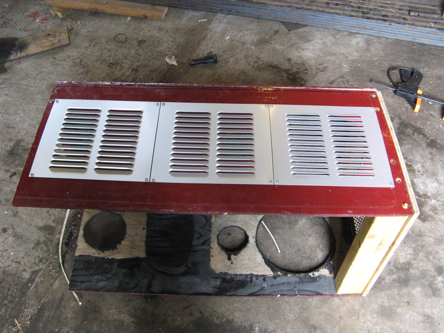
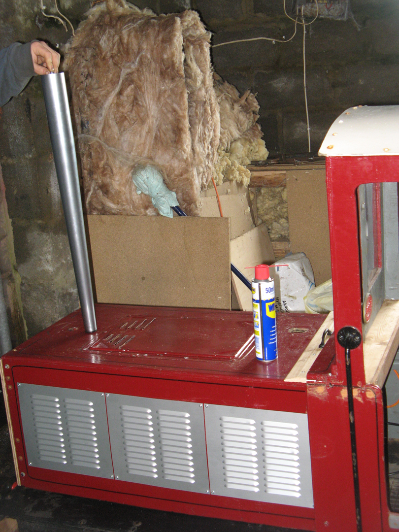
Other changes were the addition of new square grilles on the sides of the bonnet (ventilation grilles from the local DIY shop) to replace the previous odd looking round ones, a new shape front grille, and a new chimney (a 'designer' table leg!). These modifications have made Helen a much better proportioned and easier to use locomotive. There is still much hole filling and a re-paint to be done, but once this work is completed we think she will be a good looking engine.
Here's the story in pictures.......
Getting Helen Working
When Helen first arrived she was a non runner, so Ruarí set about getting her working again. The engine is an ancient Briggs & Stratton model. Fortunately the local mower shop was able to find the engine number and thus were able to supply appropriate spares. The recoil spring and rope had to be replaced before we could see if it would start. It didn't! A new spark plug and condenser, an adjustment of the points and a new air filter sponge got the engine running.
The next problem was unseizing the clutch. This was eventually accomplished using large doses of lubricant (WD40, used engine oil), the application of heat (blow torch) and plenty of brute force and ignorance, bending a puller and losing the head of the rubber mallet in the process. All that was needed after that was to adapt some old bicycle cables to connect the brake and clutch levers. After a couple of months of effort, internet research and learning as he went along, Ruarí had succeeded in getting Helen going and gained an interest in internal combustion engines.
Various bearings really needed replacing, but this drive system was surprisingly smooth, probably because it was all equally worn! For quite a long time we took a 'if it works leave it alone' approach. Over time, the forward/reverse lever became more and more difficult to operate, until eventually forward gear could no longer be selected. Being unable to go forwards at a time when we were expecting quite a few visitors was the incentive we needed to set about improving the drive system. It would also be an opportunity to add an electric start.
The original drive system was apparently from an old (circa 1970s, judging by the age of the engine) Mardyke locomotive. If anybody knows what the donor locomotive was, we would love to hear from them.
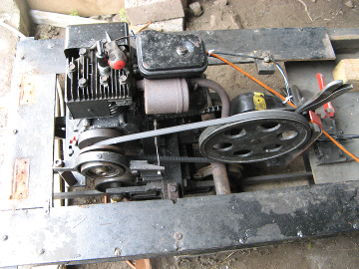
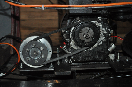
Everything is mounted on the front bogie. An ancient Briggs & Stratton engine drives a simple vee pulley clutch. The belt slips around the front (small) pulley until you operate the clutch lever (not shown in this picture) which pulls the sides of this pulley together, thus gripping the belt and providing drive. Behind the big pulley is the gearbox (with the yellow stripe on it) with the selection lever visible above. The lever has 3 positions for forwards/neutral/backwards. Final drive is via a chain to the two axles of the bogie.
Mechanical Modifications
When Helen's gearbox failed we decided to rebuild using the same general arrangement as 'Scamp', a cleverly designed locomotive by Colin Edmondson. The basic idea is that a permanent magnet electric motor and a dynamo are identical - used as a motor you put electricity in and get spinning motion out, or used as a dynamo you spin the shaft to generate electricity. You can therefore build a petrol-electric locomotive by using two identical electric motors. One of these motors is driven by a petrol engine to make it a dynamo. This dynamo is connected via a PWM speed controller and reversing switch to the other (driving) motor. Thus speed and direction control is provided without the need for a mechanical gearbox.
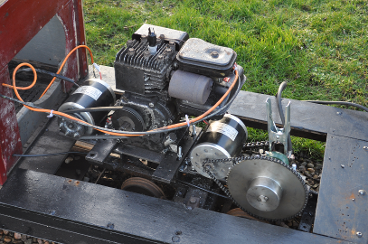
General Arrangement The petrol engine drives a motor used as a dynamo via a belt drive. The electricity generated is fed (via a speed controller and reversing switch) to an identical drive motor, which drives the large sprocket on the layshaft and then on to the driving axles and rail wheels.
Studying the Scamp spec sheet (a pdf file is provided below for viewing and/or download courtesy of Colin Edmondson), and the Scamp shopping list (an up to date version version can be found in the 'Files' section of the Scamp Owners Group on Facebook) together with some parts and advice from Colin, enabled us to convert 'Helen' to petrol-electric format.
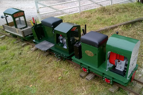
'Scamp' was originally available in kit form with a choice of three different bonnets - inspired by the Lister Railtruck (front), Orenstein & Koppel (middle) or original Scamp (on wagon). Colin has since produced other locomotives which are also ride on types, but made even smaller by using a simple electric drive. 'Scamp' and several other Edmondson designed locomotives are now sold by CMD Engineering in kit or ready to run form.

|
SCAMP spec sheet July 2016 copyright Colin Edmondson.pdf Size : 348.755 Kb Type : pdf |
Helen's ancient 2hp Briggs & Stratton engine was fortuitously of about the right size to use the same components as 'Scamp'. Using the Scamp shopping list as a guide, two 800W 36v DC motors, a 40amp PWM speed controller and a suitable reversing switch were ordered from e-bay. Most of the pulleys, belts, sprockets, chain and bearings needed for the transmission were obtained from beltingonline.com.
The pulleys for the drive belt from engine to the motor used as a dynamo are both the same size. This means the maximum engine speed (2,800 rpm) matches the rated speed of the electric motor, (i.e. maximum electric motor speed is reached at maximum engine revs), a set up which seems to work well in practice. Using a belt rather than a chain gives a quieter drive than it might otherwise be. There is also the option of adding a slipping belt clutch so that the drive could be disengaged and provide a degree of fail-safe to the controls. We decided against this option in order to simplify construction and keep the controls as simple as possible, allowing anyone to drive this locomotive. Later an easily accessible (even if you are not the driver) emergency stop button was added.
Dynamo pulley and engine pulley are the same size.
Our final drive configuration involved adding a new layshaft in place of the old gearbox, but retaining the original final drive chain. The layshaft was made of 20mm diameter bright steel bar, partly because it was a near metric size to the existing gearbox shaft it was to replace and partly because bearings for this size are often cheaper than other sizes. This has become (where possible) the KLR 'standard' size for axles etc. The existing (imperial size) sprocket was bored out to 20mm using a hand reamer which we bought from e-bay. The new sprocket that we added came with a 20mm pilot bore - the right size for the layshaft with no modification needed. It was a 76 tooth 8mm British Standard Simplex (05B-1) to match the sprocket and chain from the drive motor. We had calculated that this would provide a suitable reduction ratio to make the locomotive's top speed about 6 m.p.h. We must have made a mistake as top speed is only a slow walking pace, but we have decided that in practice this is more suitable for our purposes.

The chain drive from the drive motor to the large sprocket on the layshaft gives a low top speed, making this locomotive suitable for our short circuit and use by young drivers.
The motors (model MY1020) that we used had non-circular shafts, so we could not use standard pulleys or sprockets. These are the same motors as used in the Scamp design. Colin Edmondson was willing to sell us the parts we needed, including a special spanner for holding the sprocket in place whilst undoing the left hand thread nut. The pulley is made of three parts that are bolted together. If you have the skills and machinery, you will be able to turn the taper on the outer parts yourself and save a few pennies. At the time we were pleased that Colin offered to do this for us! The sprocket replaces the one supplied with the motor (which is not suitable for standard UK chain) with one suitable for British Standard 05B chain.
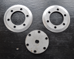
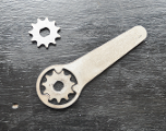
Parts obtained from Colin Edmondson - we ordered two pulleys and two sprockets so that we had spares.
Wiring is in essence simple - the wires from the dynamo are connected to the input of the PWM speed controller. The output from the PWM is connected to the drive motor via the reversing switch. It is important to make sure that the polarity of the feed to the controller is correct. If you get it the wrong way round the controller causes a short across the dynamo, which then acts as a brake and the engine cannot be started. It is likely that (because of the rotation direction of the motor used as the dynamo), the red wire is probably going to be negative and the black wire positive. This can be checked by spinning the dynamo in the direction that the engine will turn it and noting the polarity of the output using a meter.
As part of our design we had always intended to add an electric start. We found that a battery powered electric drill was capable of turning over and starting the engine when attached to the drive shaft. It was then not too big a leap of imagination to think that supplying just 12 volts to the dynamo motor (rated at 36v) could be enough to turn over and start the engine. This proved to be the case, so we have been able to follow what is apparently mainline practice and use our dynamo (or generator motor) as a starter motor too.
We added a two way (DPDT) switch to the control panel. In the 'start' position it connects a small 12 volt motorcycle battery to the dynamo motor and isolates the PWM speed controller. In the 'run' position the battery is disconnected whilst the dynamo motor powers the PWM controller. To start the engine the switch is moved to the 'start' position for a few seconds, supplying 12 volt power to the dynamo motor to turn over the petrol engine. Once the engine has fired the switch is put into the 'run' position, isolating the battery and allowing power generated from the dynamo to be supplied to the PWM controller. In the long term we hope to get more sophisticated by adding a 12 volt circuit for battery charging and so that other accessories (such as lights) can be added. For now we are content to use a mains battery charger to recharge when necessary.
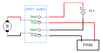
The DPDT (double pole double throw) switch isolates the PWM speed controller from the battery when starting. In the 'run' position (as above) it isolates the battery from the motor when being used as a dynamo.
Ruarí made us a smart new control panel using some sheet aluminium and his TIG welding skills. He also added a couple of extra features whilst wiring everything up. The ignition key has an 'off' postion and two 'on' positions. Position 1 is spark plug only, for normal running. An old motorcycle starter relay (added to the starter circuit between the battery and motor) allows the locomotive to be electric started only when the when the key is turned to position 2. A prominent Emergency Stop button was added, which both kills the spark in the petrol engine and isolates the electric supply from the dynamo, so the electric drive motor stops too. The lever below the Emergency Stop is for selecting forward, neutral or reverse. The switch to the left of the key is the 'start/run' switch. The speed control can be seen top right, on the flat surface.
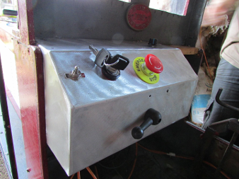
The new control panel.
If about 1 horsepower is enough power for your needs, we would recommend this kind of petrol-electric drive as simple to construct and easy to use. It's also certainly a lot cheaper than a hydraulic drive.
Click on the buttons below to read about other KLR locomotives.
