Turnouts - Points or Switches
Terminology
In the UK we usually refer to a turnout as (a pair of) points, and in America as a switch. We thought a diagram labelling the parts of a turnout as we refer to them would be a good idea. Please note that our terminology may not be correct and the names of the parts might differ from those used in your part of the world. We will try to remain consistent in our references on this page, even if we are consistently wrong!
Anyone not familiar with railway terminology will find it useful to understand the difference between 'facing' and 'trailing'. When a train traverses a turnout in a facing direction, it may diverge onto either of the two routes. When travelled in a trailing direction, the two routes converge onto each other.
Points are said to be 'trailable' if trains can travel through them from one or other of the diverging routes even if they are not set for that route.
Design
Our first couple of pairs of points were built by the late Eric Walker, the builder of our steam locomotive. He also supplied us with some of the more difficult to make parts (frogs, blades and levers) for building several more pairs of points by copying the originals. He talked us through his method of construction when we collected these items from his Kirton Light Railway.
Eric's clever design is compact (about four feet long for a 20ft radius pair of points), which is advantageous where space is limited. These points have a closed frog. This means that both running rails are continuous whichever way the points are switched. The treads of the wheels are always in contact with the rails because there is no flangeway gap at the frog (as there is with more conventional designs), which should lead to safer and smoother running. Theoretically the check rails should be unnecessary, but apparently Eric thought that the points looked wrong without them. The main tips he passed on for constructing these points were: start by fixing the straight stock rail in place, then the curved one, position the frog relative to these, then add the blades unit; the pivot point for the blades unit should be exactly half way along it's length.
Unfortunately this innovative and interesting design has become less suitable for our needs as the railway has evolved. The compact design is achieved by means of a slight reverse curve at the facing end of the points. You should be able to see this by comparing the straight stock rail to the bottom edge of the above picture. These points are therefore an asymmetric 'Y' design, which in some circumstances can lead to difficulties in designing a smooth flowing track layout. We found that as we built longer wheelbase rolling stock it seemed to prefer following the curved route in the facing direction through the points regardless of which way they were set. In the trailing direction the flanges of our rolling stock tended to just bump over the frog if the points were set in the 'wrong' direction (with the lever disconnected to allow the blades to move freely) rather than pushing the blades across , meaning that the points are not truly 'trailable'. Finally, copying a set template (albeit with left and right hand versions) was limiting our track design. We have therefore decided to make our points using conventional frogs and without the reverse curve at the facing end.
Operational Considerations
As our route developed we decided that trailable points would be a useful feature. Trailable points allow trains to run through points from one or other of the diverging routes when they are not set for that route, or in other words are set in the 'wrong' direction.
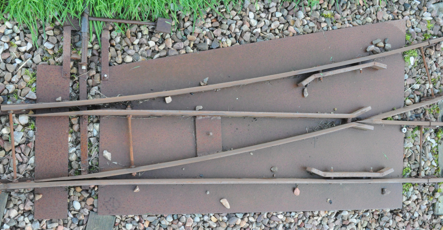
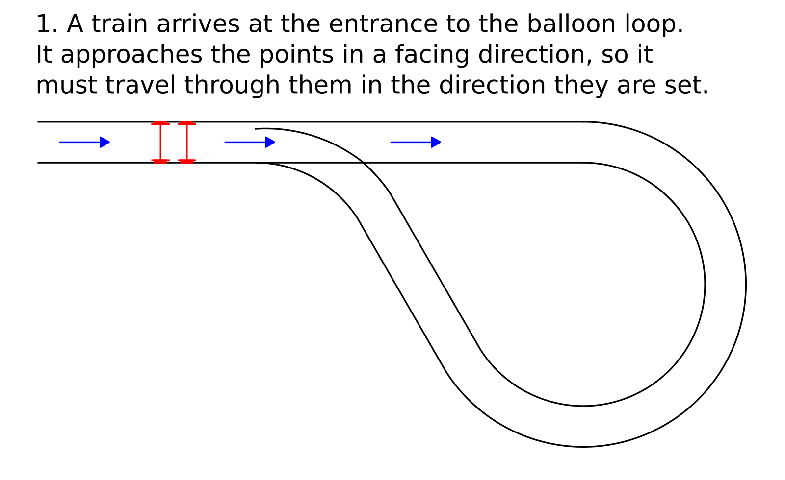
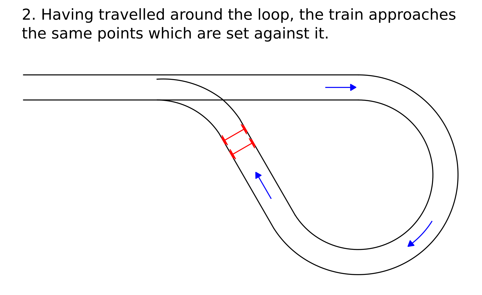
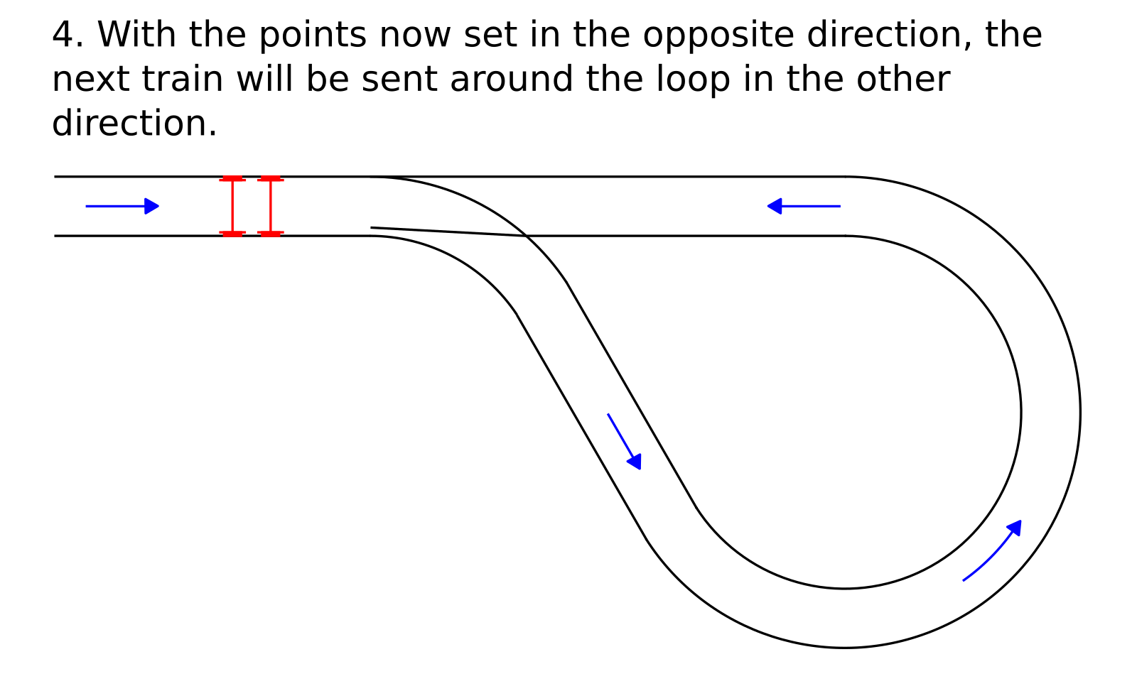
An example of where this might be useful is at the entrance to a balloon (or return) loop. A train may enter the loop travelling through the points in a facing direction, following the track around the loop to return to the same pair of points in a trailing direction. Assuming these points have not been changed they are now set in the 'wrong' direction. With trailable points the train can proceed without the need to change them. The wheels simply push the point blades across to allow passage of the train without derailing.
Of course the points are now set in the opposite direction, so the next train to approach in the facing direction will travel around the loop in the opposite direction. This could be used to advantage as a form of automatic route variation. In practice it is a good idea to add a mechanism to ensure the point blade is pushed fully home against the relevant stock rail each time the points are changed.
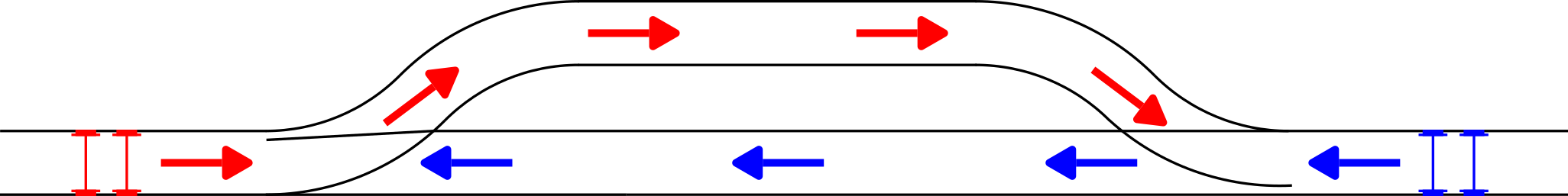
'Sprung' points add further possibilities. A spring can be used to make trailable points self-restoring to a predetermined direction. This can allow a degree of automatic route setting. For instance, at each end of a passing loop the points could be sprung to send trains into opposite sides of the loop according to their direction of travel. Exiting the loop trains can drive drive through the 'wrongly' set points in the trailing direction. Thus the two trains can pass each other without having to change any points.
Using trailable points means trains can follow routes that would otherwise require changing points before proceeding. Careful planning can allow a degree of automated route operation. To further increase versatility we are considering installing driver operated points. By positioning the point lever within reach of the driver and some distance ahead of the pair of points that it controls, the driver can control the route of the train as it travels around the circuit. This would allow one person operation of the railway, but a possible disadvantage would be that others (such as passengers) might be tempted to switch the points. Positioning the lever a minimum distance of a full train length before the points would ensure that even if this did happen, it wouldn't be whilst a train was traversing the points. Wireless control of electric motor switched points (from a mobile/portable device that could be carried by the train driver when no signalman is available) could be another possibility............. but we're getting ahead of ourselves thinking about such things.

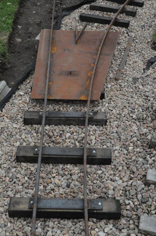
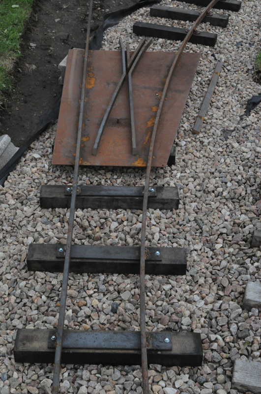
You may have noticed we haven't exactly followed the sequence described in the photos above. This is because we quickly laid out previously fabricated parts to produce the first four pictures, rather than taking photos as we actually built the points. The final picture shows the completed pair of points with the blades unit welded up and fitted in place. If you look carefully at the picture of the completed pair of points (last picture in the sequence above), you should be able to see the short lengths of angle iron welded to the base plate where the blade unit meets the wing rail. We have found this to be a useful feature of the design that ensures good alignment whichever way the points are switched.
In practice we find it best to cut each part longer than it will need to be, partly because we cannot bend right to the end of a piece of rail, and partly to give ourselves room for error - we can always shorten a piece to exactly fit but we can't make it longer! We generally find it easier to bend and cut all the pieces to size before doing any welding. Once we have made a 'kit of parts' we can check and double check that everything fits together correctly. Plenty of rail gauges and clamps help make sure everything is held in the correct place, but it is amazing how small an inaccuracy or misalignment can be detected by eye. In our experience if something looks wrong then it probably is wrong!
When making relatively sharp radius points it is important to note how gauge widening influences other dimensions. It took this author a long time to appreciate that a check rail helps guide the wheel along the opposite rail, so it is the relationship between a check rail and the opposite running rail that helps ensure the smooth passage of a wheelset through a pair of points. When the track gauge "B" is widened by a certain amount (y), the flangeway "A" widens by the same amount (y), so that the distance from the running rails (the rails the wheels run along) to the back of the opposite check (or wing) rail ("C", the check gauge) remains the same. In other words, the check gauge "C" remains constant whatever the amount of gauge widening. Hopefully the diagrams below help to make this clear.
The most important place to make sure you have got your check gauge measurement correct is from the tip of the frog to the back of the opposite check rail. The aim is to make sure that as the wheel on the outside running rail traverses the frog gap the opposite wheel just brushes the check rail. This ensures that the wheels are guided safely past the gap and onto the correct side of the frog. Talking of guiding the wheels, the 'bent bits' at the ends of the check rails are 3 or 4 inches (75mm - 100mm) long with only a gentle bend. The idea is to gently draw the wheels into the correct position rather than to suddenly yank them sideways.
You may have noticed in the pictures of our completed pairs of points that the design of the blades has changed over time. Originally the bar was cut all the way through to create a taper the full depth of the rail. This was done for us using a milling machine and we found the thin end of the taper was vulnerable to damage. We now cut our own blades using a grinder. It is not necessary to taper the full depth of the rail, just the top centimetre or so to allow the wheel flanges to pass through.
Producing blades in this way means they are 'handed' - one blade needs to be a mirror image of the other. You cannot simply turn the blade over to use on the other side in the same way that you can with tapers cut to the full depth of the rail. Take care to double check your second blade really will be mirror image of the first one before cutting it! The final stage of blade making using this technique is to bend the blade at the point where the taper runs out, to make the running edge lie in a straight line right along the length of the blade. The end of the blade only needs to be moved over by the width of the blade. The best way of judging when you have got it straight is by eye. You should do this for both the straight and the curved blade, then bend the curved blade as needed. Rounding off the tip of the blade at the very end of the taper will make it less prone to damage, and gentle grinding to produce a radiused edge where the wheels will run improves running.
When welding up the blades unit it is easiest to align the straight rail, so we fit this in place first. It is then necessary to move it to the open position before fitting the curved rail in place. Although the gap between blade and stock rail only needs to be maybe a little more than the flangeway (say 8mm if using the 7 1/4 Gauge Society standards), we have found a larger gap (12mm or maybe even more) works better, especially where the turnout is in the middle of a curve with the straight side leading off on a tangent. Of course the gap you choose may be limited by the throw of point lever you choose to use, so if you intend to buy in point levers check out their maximum throw.