Track Building - The Idea
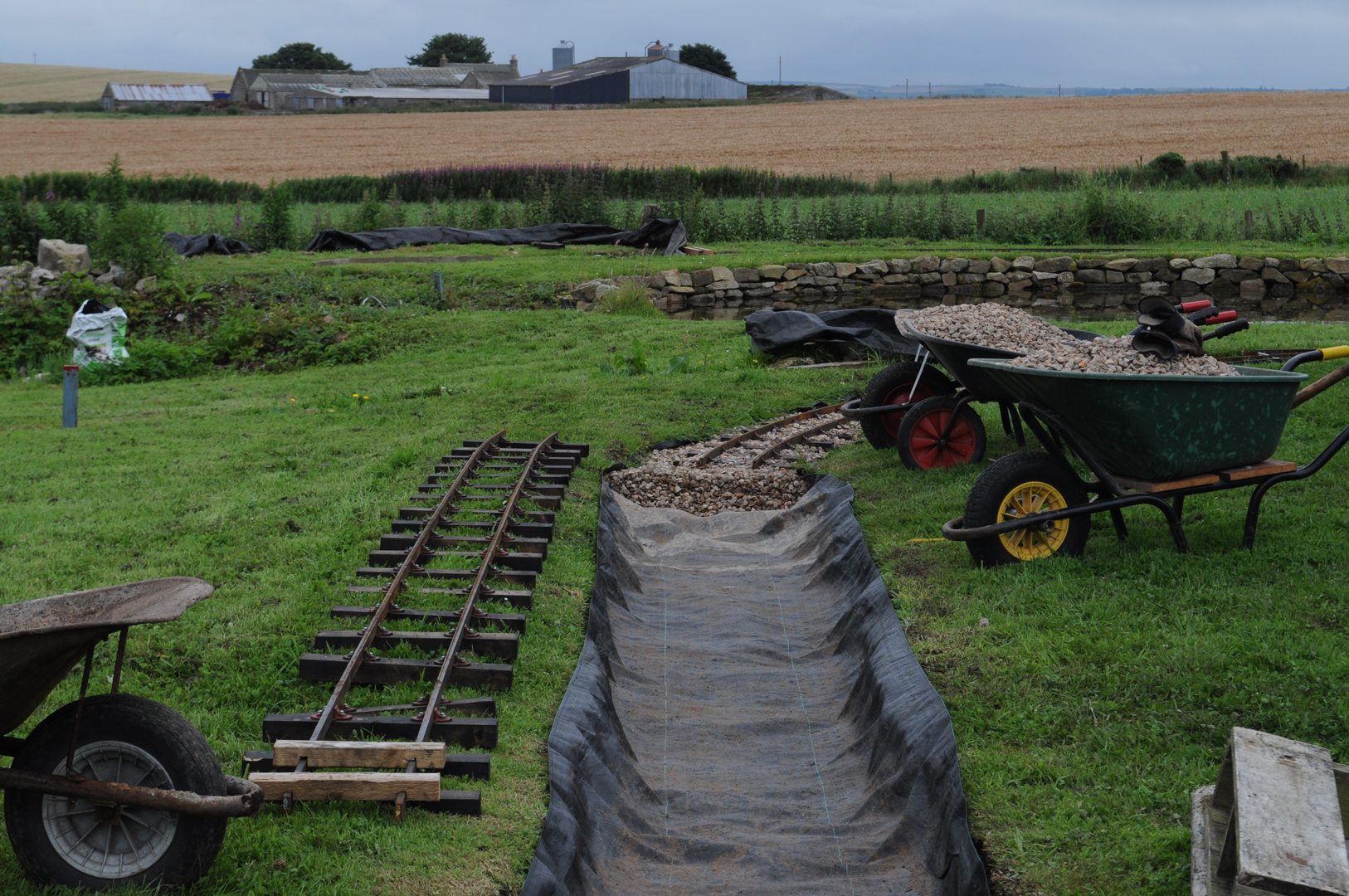
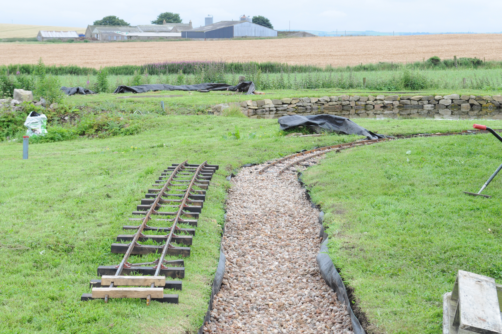
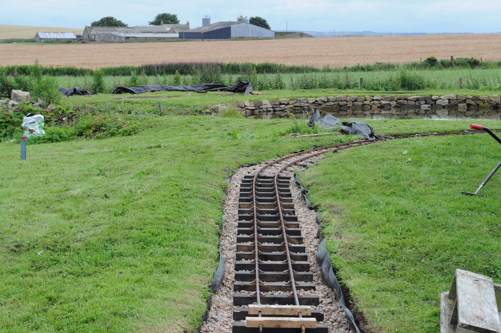
Our method for building track is (in theory) straightforward. Simply dig a shallow trench following the chosen route, line with weed suppressing fabric, part fill with ballast, place a track panel on top and add more ballast to hold the track in place.
Of course, things aren't that simple in practice. A site survey was made to help decide where the railway should go and a level survey was used to make sure gradients weren't too steep. Decisions had to be made about what materials to use and track panels were constructed. Last (but certainly not least), some unexpectedly large physical obstructions had to be moved in the process of 'simply' excavating the track alignment. What follows is a description of how we made our track.
Surveying and Marking Out
A site survey was made to produce a plan showing the boundaries and main features of the site to help decide on the route for the railway. A rough idea of the relative levels of different parts of the site was determined using a cheap laser level and a home made sighting board. The Ride on Railways web site has a useful section on building a garden railway including Site Survey and Level Survey pages. Should you be considering making your own level survey, the first piece of advice given is most important - never assume a level (the tool) is accurate, always check before using it.
The site survey proved useful for armchair planning of railway and garden features, and for estimating quantities of track materials required. The level survey helped establish a datum level to work from.
Once the general route of the railway had been decided, marking out on the ground could begin. The sharpest curves in the most limited space were laid out first as these were the areas where there was least room for tweaking or modification later. Sharp curves were measured out using a peg and string to make sure they were the intended radius, whilst more sweeping curves were determined by what looked pleasing to the eye .Where possible a short length of straight was placed between places where the direction of the curve reversed.
Initial marking out was by placing painted stones every few feet along the centre line of the proposed route. Before finally marking the route on the ground we found using a long length of garden hose to mark the centre line was a good way of checking we had produced an accurate curve that looked 'right' with smooth transitions onto the next section. Once we were happy with the alignment, turfs were stripped to the width of the track bed. If stripping turfs by hand it is much easier if one person does the spade work and another rolls the turf as it comes away from the ground. If you are the turf roller do wear proper protection - at least proper boots, some hefty gloves and maybe shin pads if your spade person is as (un)skilled as this writer to avoid the possibility of a trip to casualty!
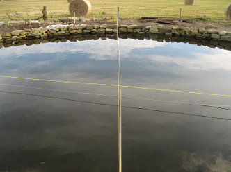
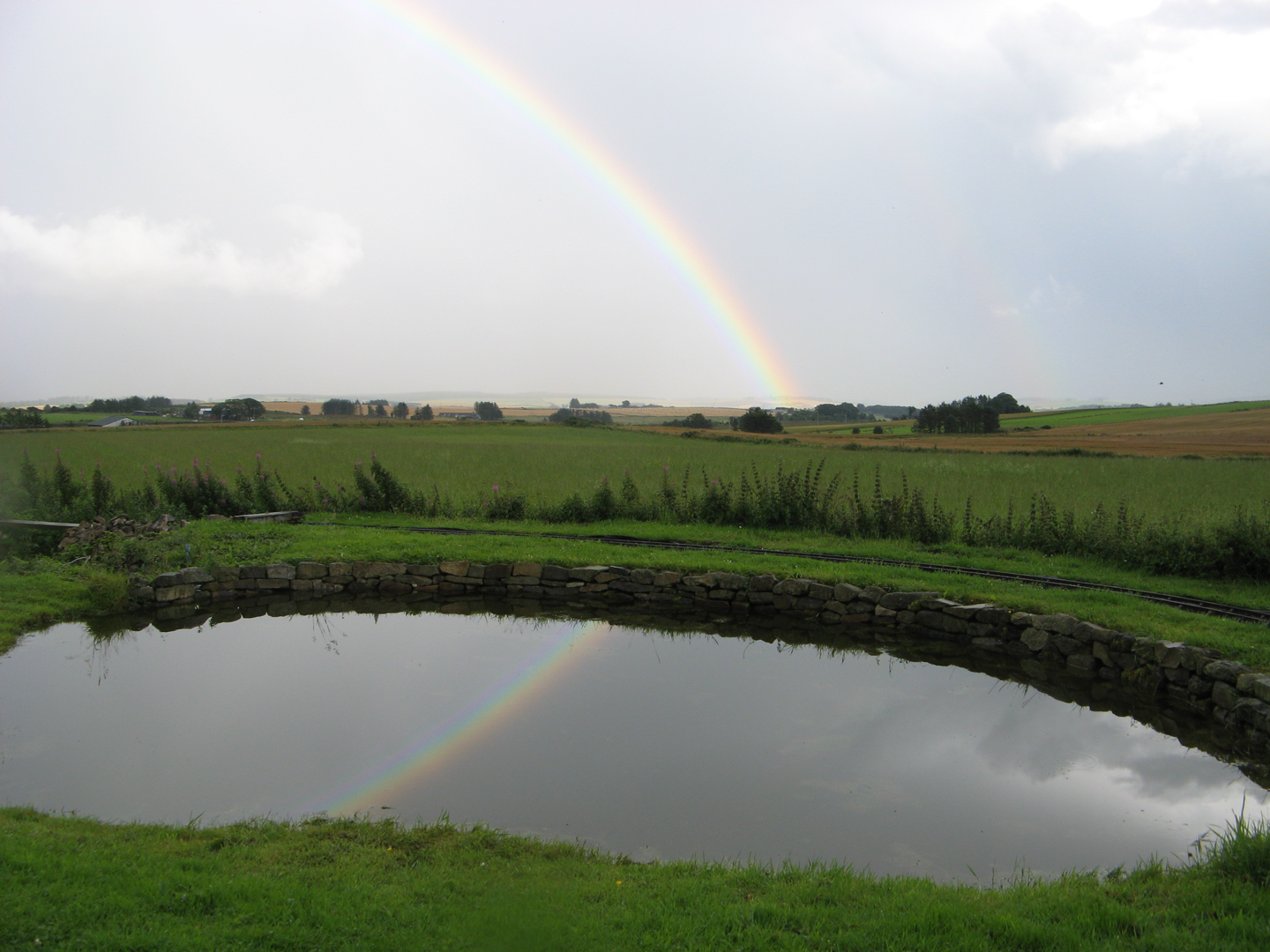
Marking out around the pond was tricky. The centre of the curve was in the middle of the pond, and a stake couldn't be driven in because of the liner. Mark out your railway before building a pond!
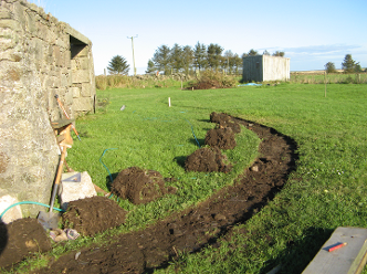
Turfs stripped to mark the track alignment.
Track Components
Major considerations when deciding what track to use were keeping construction costs to a minimum, whilst providing an attractive looking, easy to maintain track formation that is robust enough for our relatively large miniature trains. These are the materials we used and why we chose them.
Weed Suppressing Fabric. We used 1 metre wide weed suppressing fabric to try and prevent the weeds immediately springing up through our newly laid track. Available in 100 metre long rolls from garden centres or the internet, e-bay etc.
Ballast. Ideally we would have used crushed granite, which you might expect to be easily available so close to Aberdeen 'the granite city'. 20 mm crushed local stone proved to be much cheaper. Information from various web sites suggested that the most important thing was to choose a sharp stone that would interlock to hold the track in place whilst still allowing drainage. A useful test for any stone's suitability is to rub the flat surfaces of two stones together and check that they grip together, rather than slide across each other.
Rail. Numerous sizes and types of rail section are available and opinions vary about the pros and cons of steel versus aluminium rail. We decided that 30mm x 12mm mild steel bar as used on many club tracks would be adequate for our purposes. It is a lot cheaper than profiled steel rail, but strong enough for fairly heavy trains. The track will not see very frequent use, so wear and tear on wheels due to the squarer profile than 'proper' rail shouldn't be significant. Steel was preferred to aluminium because it can be easily welded, the harder material will suffer less wear and tear, and its strength means fewer sleepers over a given length of track are required. Steel has a lower rate of thermal expansion than aluminium, so less allowance needs to be made for rail expansion on hot days. Finally, it has been suggested that steel is less slippery when wet than aluminium rail.
Sleepers. As the railway is narrow gauge in character, the sleeper size and spacing reflects this. Sleepers are approximately 18" x 3" x 2" (actually a near metric approximation but I can't remember what that was), spaced at about one foot centre to centre. They are made of 'treated' softwood, (though the salesperson couldn't tell me what it was treated with) which was given an additional thorough soaking in a mixture of creosote and used engine oil. These sleepers cost about half as much as commercially produced plastic sleepers of the same size. They should last a reasonably long time as the ground is well drained.
Chairs. PNP Railways produce plastic sleepers for bar rail which make attaching the rail to the sleepers a lot easier than welding thousands of metal tags to the rail, and they look better too. The chairs are simply clipped into place on the rail and as you screw them down onto the sleeper the shape of the moulding causes them to grip the rail sufficiently as long as you avoid walking on the sleepers . Another advantage of these chairs is that they are cleverly designed to allow for automatic gauge widening on curves. The shape of the moulding is slightly asymmetrical, so fixing a chair one way round will give the correct nominal gauge, but turning it around 180 degrees achieves gauge widening. This is explained more fully in the PNP instruction leaflet for these chairs. The design of chairs for 30 x 12mm flat bar rail has changed slightly since we bought ours, but the idea remains the same. The chairs we used now appear to be marketed as suitable for 1/2" x 1" hot rolled steel bar and are considerably more expensive than the newer design.
Fishplates. These are 25mm x 3mm angle iron, welded to the rail at one end and bolted at the other. The bolt holes at the non welded end of the fishplate are drilled slightly oversize and a small gap is left between the rail ends to allow for thermal expansion.
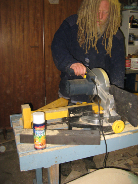
Sawing sleepers to length. An end stop screwed to the table ensured they were all the same length.
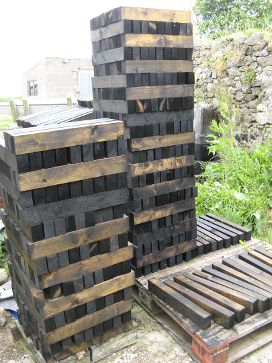
Prepared sleepers await the track laying gang.
Track Building - In Practice
Groundworks
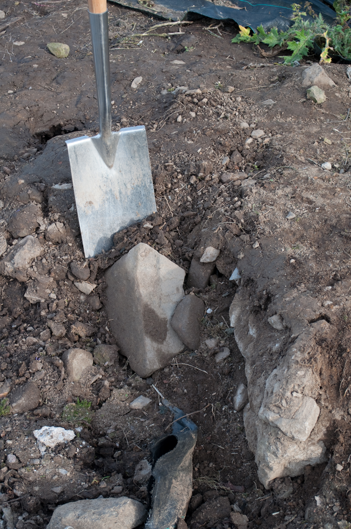
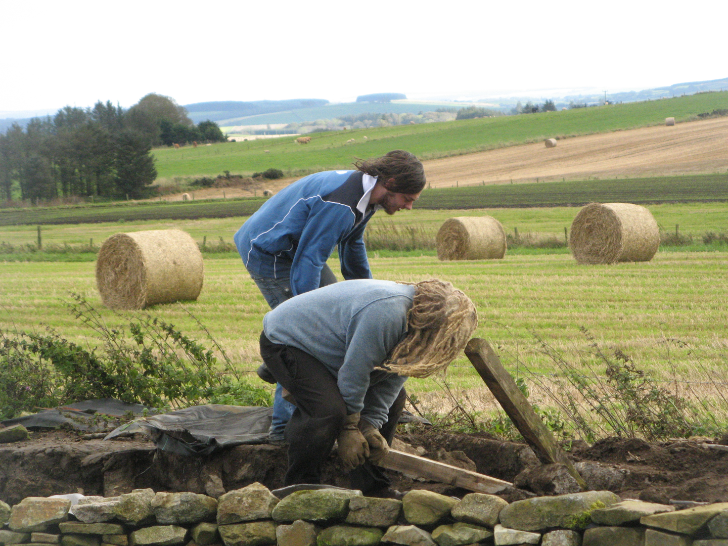
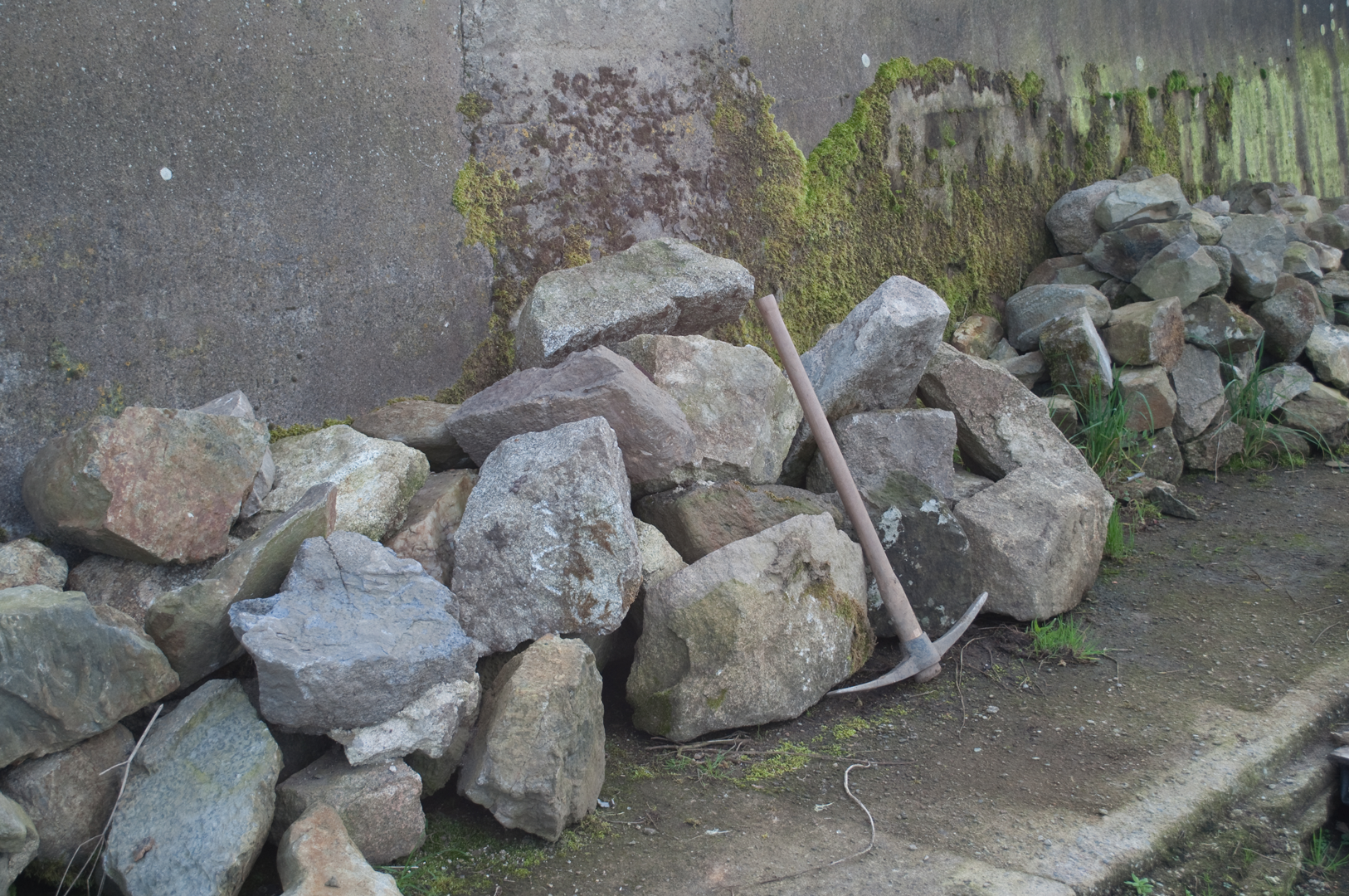
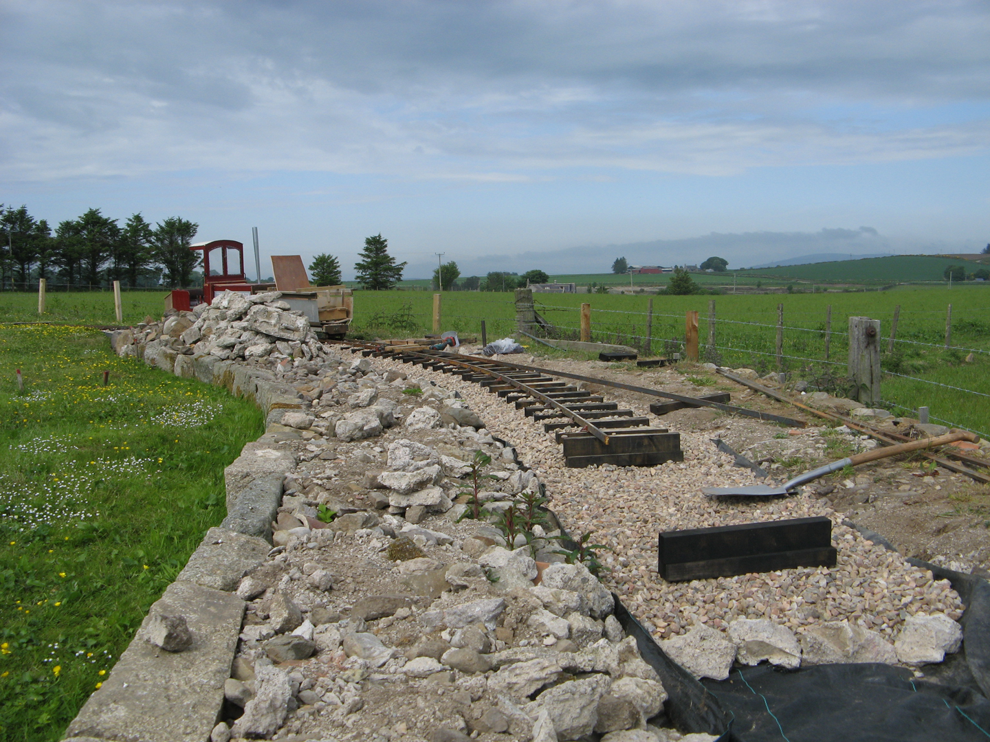
The ground at our site consists largely of long since demolished outbuildings mixed with naturally stony soil. As mentioned previously, 'simply' excavating the track bed was not that simple! Quite often what appeared to be a fairly small stone sitting just a little too high turned out to be a heavy (too heavy for one person to lift) rock or lump of concrete, usually wedged in place by similarly heavy lumps of rock/concrete. Occasionally it was possible to smash off a piece of the offending obstruction, but most of the time much digging and/or pick axe work together with the use of long levers was needed to achieve a satisfactory level. The largest lump moved turned out to be twelve extremely dense concrete blocks cemented together and covered in an impenetrable and unbreakable render! At least all this excavation work provided plenty of material for building embankments and the nicer stone could be used for scenic features. This short paragraph hardly seems to do justice to what has been a very large proportion of the most difficult work during construction of the railway!
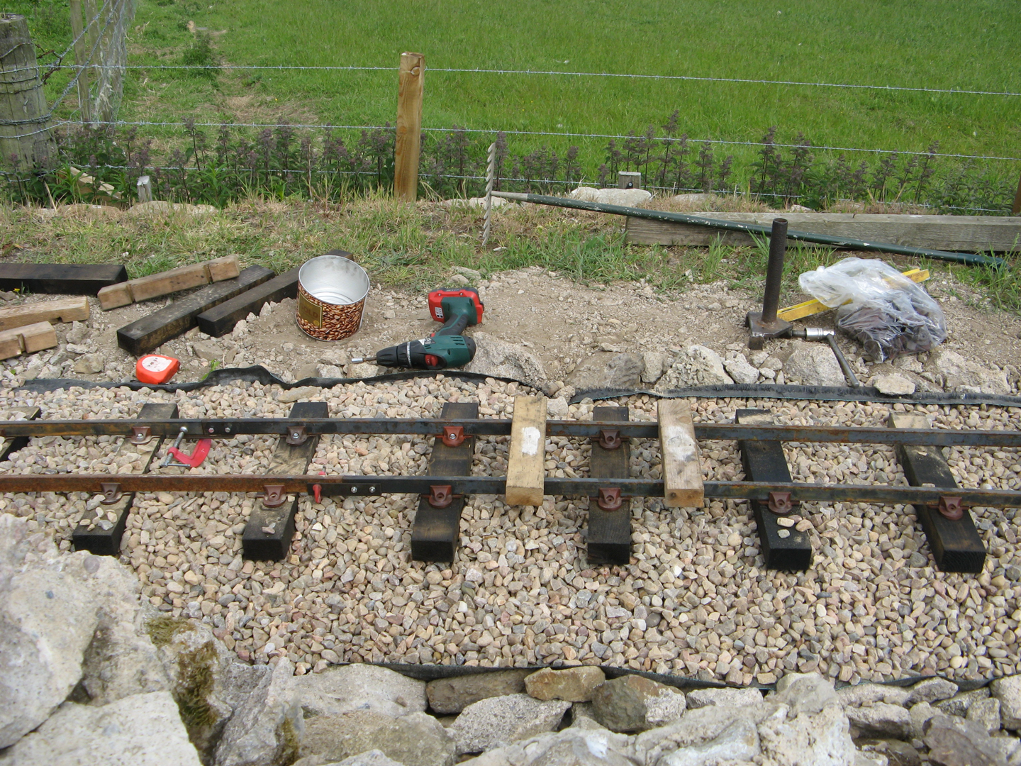
Ready to lay track panels
With the trackbase prepared, it was time to move on to the construction of the track itself. Initially we had thought that it would be a good idea to prepare ready to lay track panels. By pre drilling four holes in each sleeper we would be able to accurately locate the rail chairs relative to the sleepers. We used a sample PNP Railways plastic sleeper as the pattern for our sleepers and built a simple jig to enable us to easily drill the sleepers in the correct places. To complete a track panel chairs could be clipped onto the steel bar 'rail' at the required spacing, prepared sleepers placed in position underneath, and the chairs screwed to the sleepers thus securing the chairs to sleepers and rail in one simple operation.
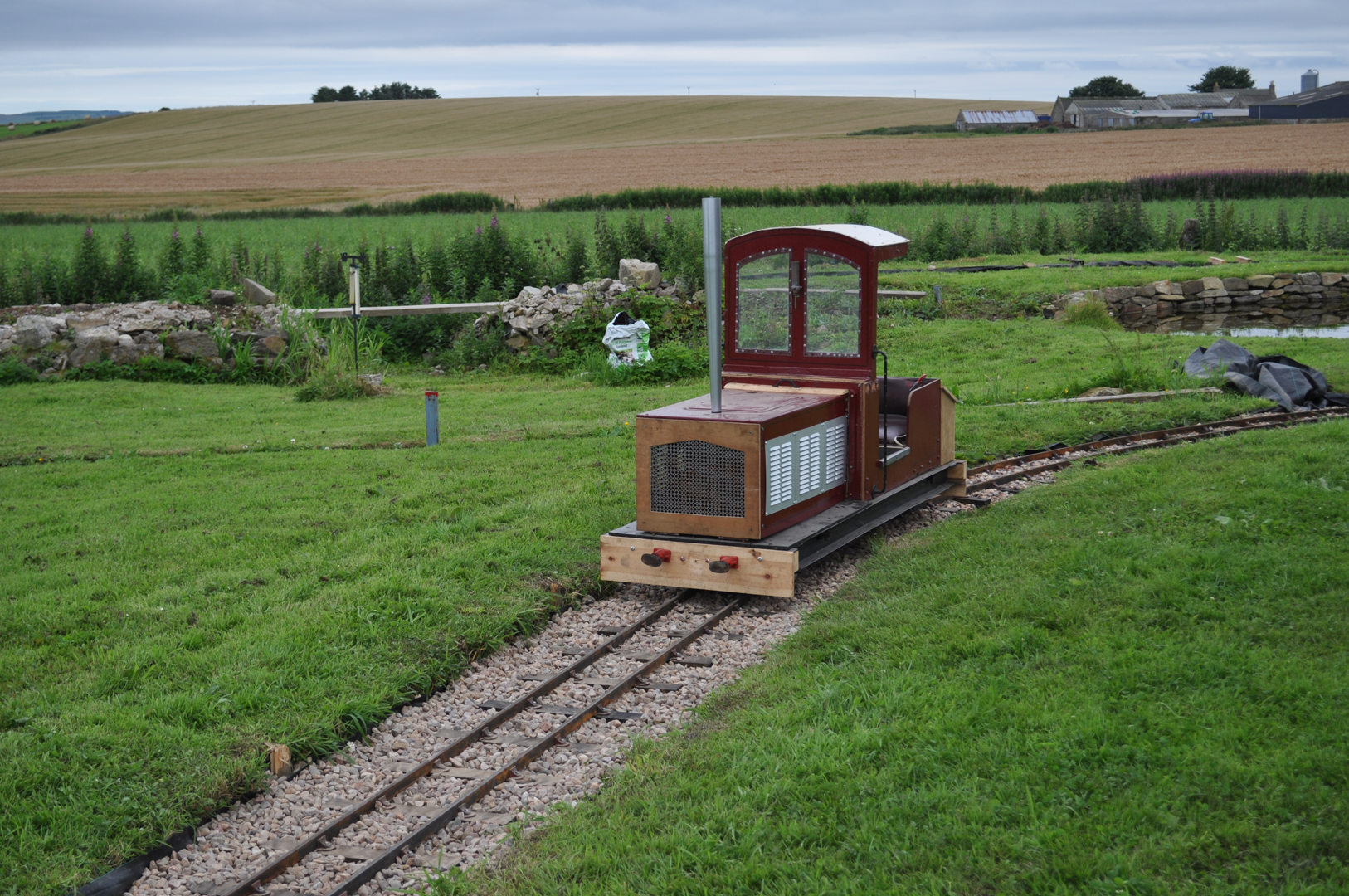
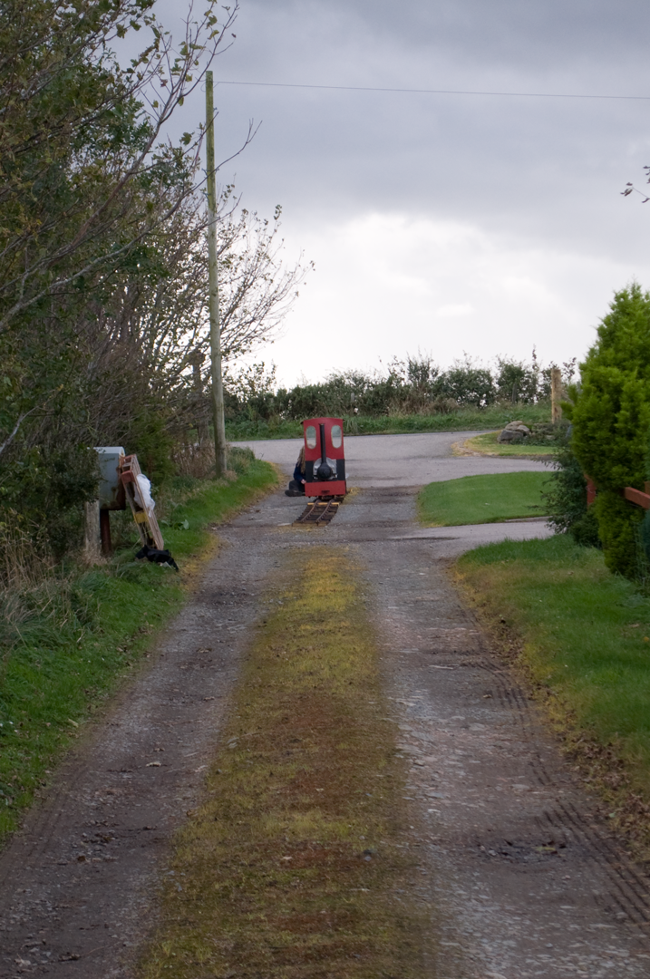
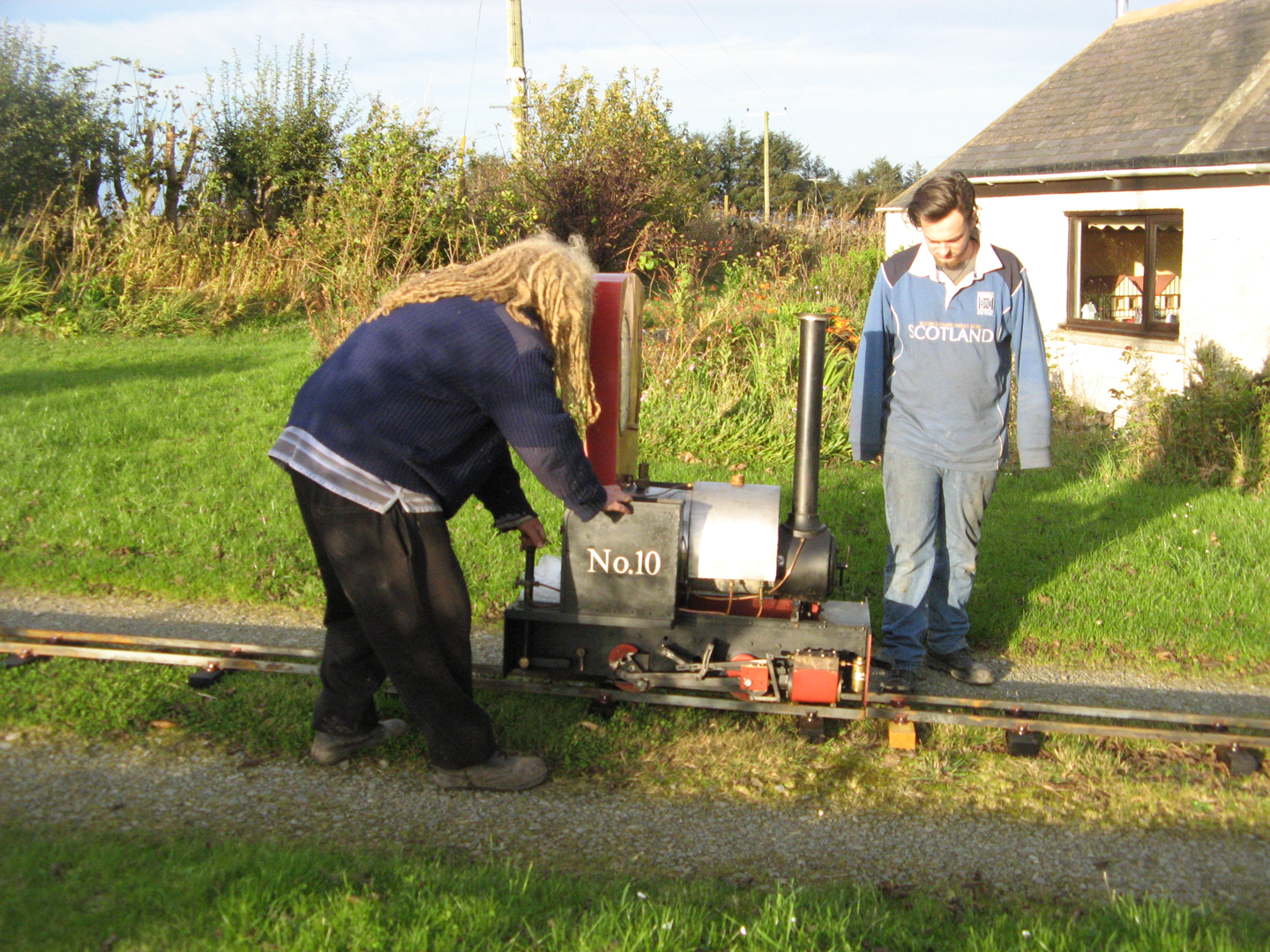
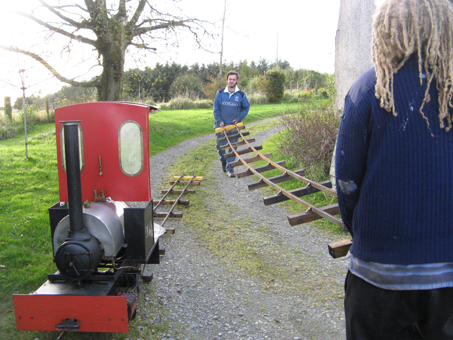
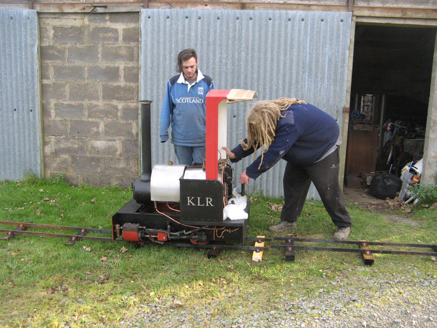
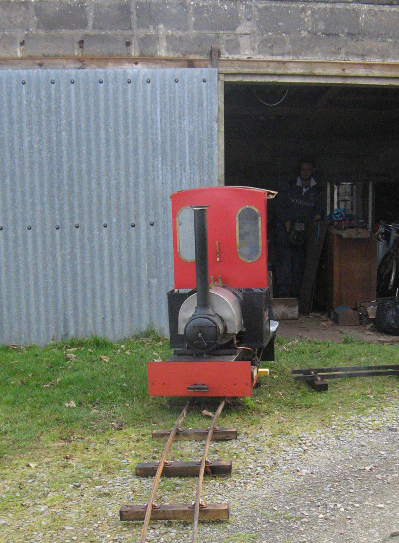
We made up a couple of straight track panels using this method and soon had to use them when our steam engine was first delivered. The lorry driver was unwilling to drive up our entrance track from the road, so No 10 was unceremoniously dumped by the roadside a few hundred yards away from the house. In order to get the engine to the house we had to use the track panels by rolling the engine onto first one then the other, leap-frogging the panels every 20 feet (the length of the steel bar 'rail') up the entrance track. This experience taught us that track panels ready made in this manner require quite a bit of care when moving them. Any accidental twisting of the panel or bumping sleepers on anything could lead to the chairs grip on the rail being loosened and occasionally sleepers coming right off. It also showed us that bending these ready made track panels to the sharp curves envisaged for the railway would be impossible.
A Learning Curve
Having decided that ready to lay track panels were not such a good idea, our track has been built 'in situ'. We had been advised that we could 'just spring' curved rails into position (holding them in place with garden forks or similar until ballast is packed around the sleepers), but we found this difficult in practice. Our ground conditions make it virtually impossible to just jab a fork in the ground wherever you need to! We also felt that pre-bending the rail would help ensure each length of track would remain following the intended curve, rather than tending to spring itself straight again and forming 'thrupenny bit' (or fifty pence piece in decimal) curves.
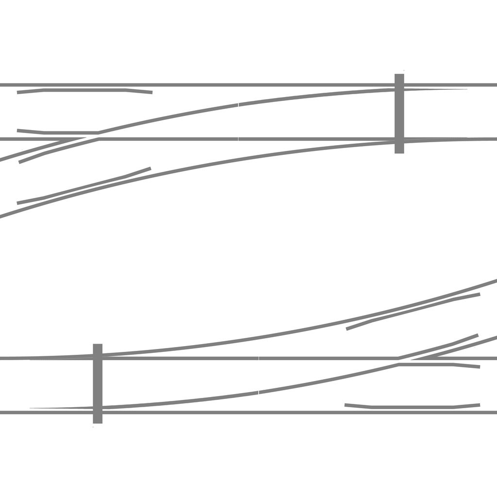
We found that pre-drilling four holes in the sleepers in an attempt to mimic the PNP plastic sleeper pattern was not very accurate when using a cheap wobbly inaccurate drill stand. (Sounds like a bad workman blaming his tools or is it a case of you get what you pay for? We're pleased to report that buying a decent pillar drill seems to have led to greater drilling accuracy).The holes sometimes being far from where we wanted them had inevitably led to unacceptable gauge variations. Our solution was to make up some accurate track gauges by cutting 12mm wide slots (to fit over the 12mm bar rail) exactly 7 1/4 inches apart in a piece if spare timber. We also made gauges to allow for 1/16" and 1/8" gauge widening, making sure they were labelled to avoid confusion. These (plus others to mark where check rails should go) have proved invaluable both for plain track and point (or switch) building. So far our wooden track gauges have proved accurate enough, but we do take the precaution of periodically checking them for wear and replacing if necessary. Commercially available laser cut steel track gauges for different rail types (and for other gauges besides 7 1/4 inch) are now available from several suppliers. If you are using the same 12mm thick bar as we use and are intending to make your own points, you might consider the set of gauges designed by Colin Edmondson and sold by MRW a worthwhile investment to ensure accuracy in all your track building.
The home made wooden track gauges. The one on the left of the picture is holding the rails to the correct gauge, the one on the right shows the slots cut to hold the rail in place.
Making Tracks - our permanent way
In light of the above comments, our track building procedure has now evolved to be as follows:-
- Bend a length of rail (if necessary) to approximately the correct curve for the inner rail.
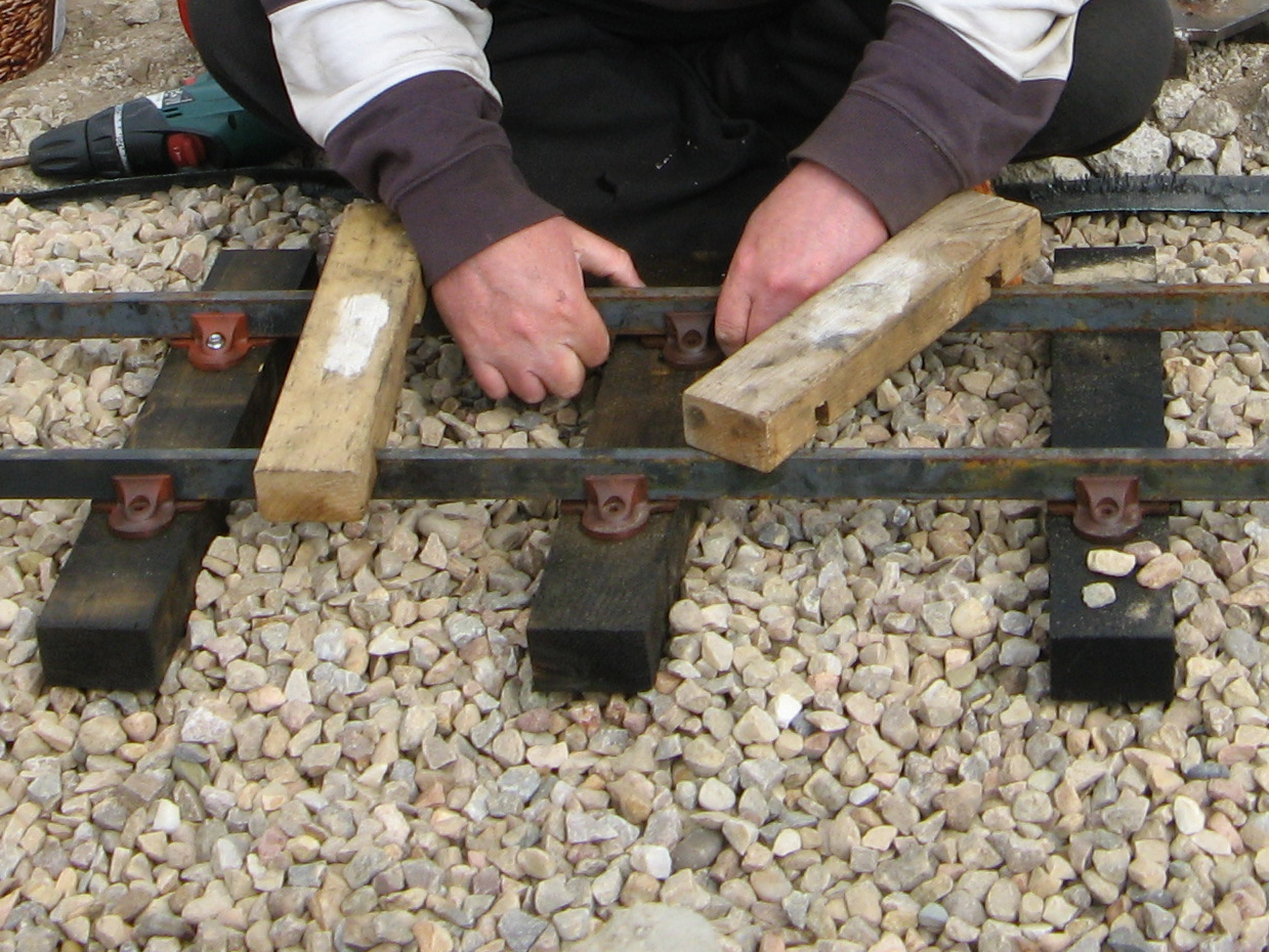
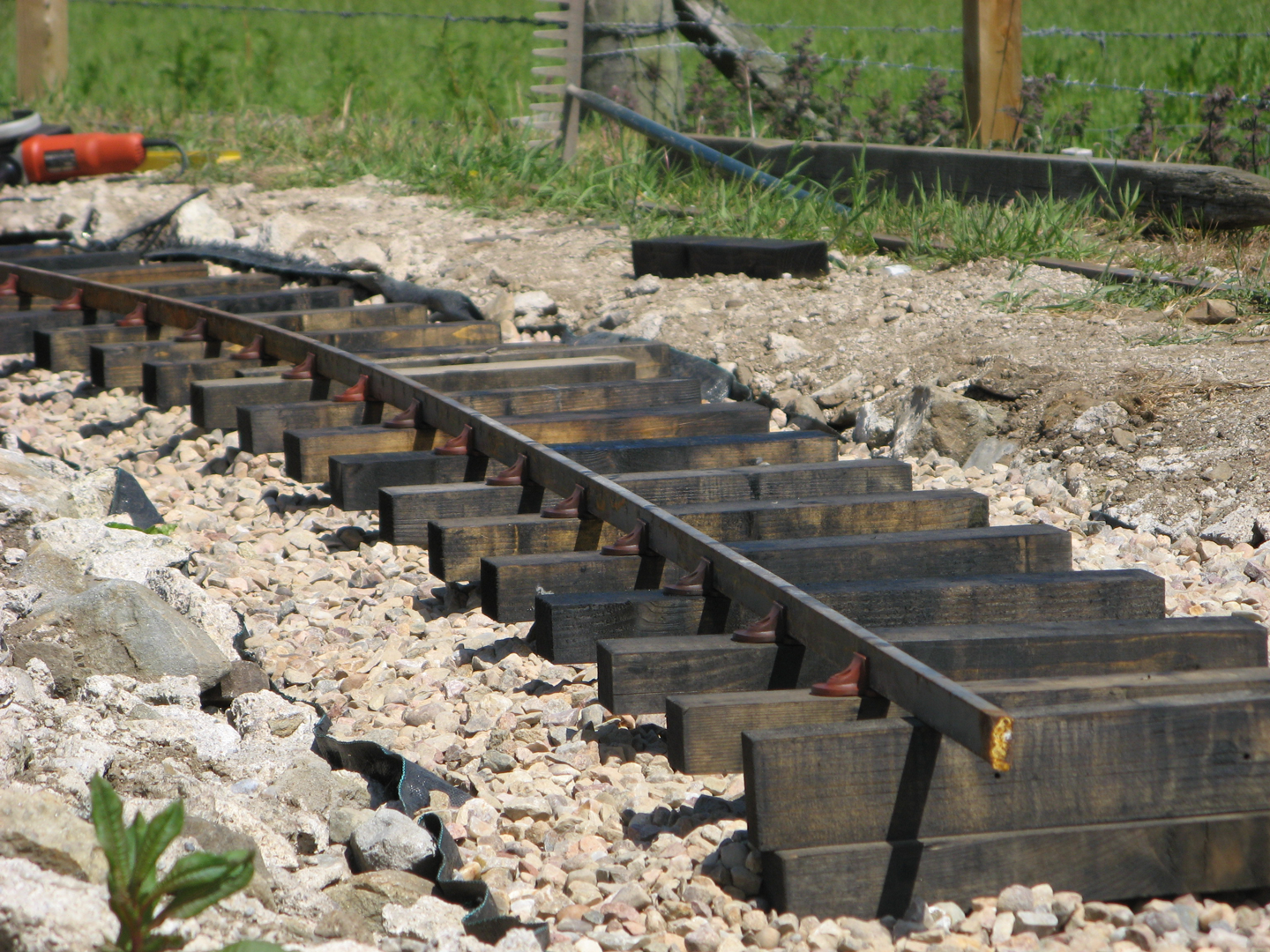
- Clip on chairs to this rail at the correct spacing. In our case this is 1 foot centre to centre. Since the PNP chairs are of an asymmetrical design it is important to make sure you clip them on consistently the same way around. We usually fix them with the arrows pointing inwards, which allows for subsequent gauge widening using the same screw holes if found necessary.
- Screw chairs to sleepers using one screw only. Instead of pre-drilling all the sleepers with 4 holes as originally planned, we now only pre-drill one hole in each sleeper to mark where this first screw needs to be located. This part of the process is more easily accomplished with the rail temporarily supported on a few additional sleepers laid on their sides. This allows you space to easily position the sleepers that you are fixing to the chairs rather than working against the weight of the rail.
- Check the rail follows the intended curve, it is properly seated in the chairs and that the sleepers are sitting level (or at whatever degree of cant you deem appropriate to the radius of curve) and the ballast is well packed underneath them.
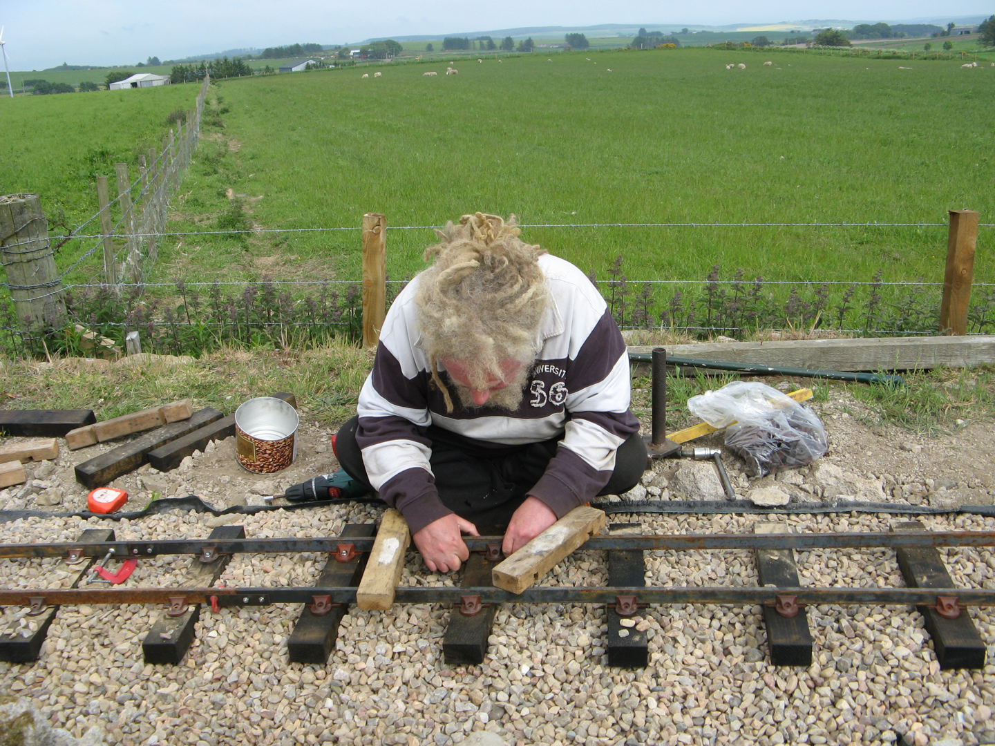
- Beginning at one end of the section of track, bend the outer rail using the appropriate rail gauges positioned both before and after the sleeper you are working until the rail fits accurately in place. Clip a chair in place and fix it to the sleeper using one screw only.
- Check the track is laying as it should. If satisfied (i.e. rail properly located in chairs, correct sleeper spacing, gradient, cant, gauge, alignment) add the second screws to complete fastening of the chairs to the sleepers. We don't add the second screws until this stage to allow for a little tweaking if needed.
- Top up ballast to the top of the sleepers.
The whole procedure is a lot less complicated than the explanation. The pictures below should help clarify anything that isn't clear.
Rail Bending
We use a 'Jim Crow' to bend the rail. This is a very useful tool, but it does take some time to bend a twenty foot section of rail. The two 'claws' fit over the rail and the hefty screw is tightened against the opposite side to produce a bend. This procedure is repeated every inch or two along the whole length of rail to make a (hopefully) smooth curve. If you find you have bent the rail too far, simply bend back the other way to correct. Different bits of rail can be easier or more difficult to bend due to variations in the steel bar, but a bit of practice and you soon get a feel for how much force to use.
It would probably be quicker to use a roller bender similar to this one from PNP Railways, but it would need some modification to work with our flat bar rail. As things stand,each time a new section of rail needs bending it seems quicker to just get on with it, rather than make a tool that might save time and effort in the long run! Some people know how to make work for themselves, don't they? The KLR budget won't stretch to simply buying one.
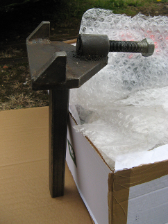
Jim Crow rail bending tool.
Click on the button below to go forward to: